FREQUENCY TO VOLTAGE CONVERTER

>> Wednesday, June 23, 2010

Description.
LM331 is basically a precision voltage to frequency converter from National Semiconductors. The IC has a hand full of applications like analog to digital conversion, long term integration, voltage to frequency conversion, frequency to voltage conversion. Wide dynamic range and excellent linearity makes the IC well suitable for the applications mentioned above.
Here the LM331 is wired as a frequency to voltage converter which converts the input frequency into a proportional voltage which is extremely linear to the input frequency. The frequency to voltage conversion is attained by differentiating the input frequency using capacitor C3 and resistor R7 and feeding the resultant pulse train to the pin6 (threshold) of the IC. The negative going edge of the resultant pulse train at pin6 makes the built-in comparator circuit to trigger the timer circuit. At any instant, the current flowing out of the current output pin (pin 6) will be proportional to the input frequency and value of the timing components (R1 and C1). As a result a voltage (Vout) proportional to the input frequency (Fin) will be available across the load resistor R4.

Circuit diagram.


Notes.

  • The circuit can be assembled on a vero board.
  • I used 15V DC as the supply voltage (+Vs) while testing the circuit.
  • The LM331 can be operated from anything between 5 to 30V DC.
  • The value of R3 depends on the supply voltage and the equation is R3= (Vs – 2V)/ (2mA).
  • According to the equation, for Vs = 15V, R3=68K.
  • The output voltage depends on the equation, Vout = ((R4)/(R5+R6))*R1C1*2.09V*Fin.
  • POT R6 can be used for calibrating the circuit.


Read more...

LIGHT TO FREQUENCY CONVERTER

Introduction.

Here is the circuit diagram of a effective light to frequency converter circuit that can be used for variety of applications such as light intensity measurement,fun etc.

The circuit is based on TLC555, the CMOS version of famous timer IC NE 555. A photo diode is used for sensing the ligt intensity.The timer IC is wired in astable mode.The leakage current of the reverse biased photo diode is proportional to the light intensity falling on it.This leakage current charges the capacitance C1.When the capacitor voltage reaches 2/3 of the supply voltage the out put (pin 3) goes low.As a result the capacitor discharges through photo diode .When the capacitor voltage reaches 1/3 the supply voltage the out put (pin 3) of IC goes high.This cycling continues and we get a frequency at pin 3 proportional to the light intensity falling on the photo diode.


Circuit Diagram & Parts List.


Notes.

  • With the given components the frequency varies from 1KHZ @ complete darkness to 24 Khz @ bright sunlight.The frequency range can be changed by using different values for C1.
  • Use any general purpose photo diode for D1.


Read more...

CABLE TV AMPLIFIER

>> Saturday, June 19, 2010

Description.
This is a very simple cable TV amplifier using two transistors. This amplifier circuit is most suitable for cable TV systems using 75 Ohm coaxial cables and works fine up to 150MHz. Transistor T1 performs the job of amplification. Up to 20dB gain can be expected from the circuit.T2 is wired as an emitter follower to increase current gain.

Circuit diagram.


  • can be assembled on a Vero board.
  • Use 12V DC for powering the circuit.
  • Type no of the transistors are not very critical.
  • Any medium power NPN RF transistors can be used in place of T1 and T2.
  • This is just an elementary circuit. Do not compare it with high quality Cable TV amplifiers available in the market.


  • Read more...

    plant moisture level monitor

    >> Saturday, June 5, 2010

    Description.

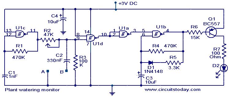
    Here is a simple circuit that will give a visual indication when the soil water level inside your flower pot goes low below a certain limit.

    The U1C and associated components are wired as an oscillator producing a 2KHz square wave. This square wave is given to one gate input of U1D via a variable potential divider former by R1 and R2.When the resistance across the probes A and B are low that is when soil moisture level is high, the C2 will divert the square wave to ground. The output of U1D will be high. The U1 A inverts this high state to low and so the IC U1B is blocked from producing oscillations. The LED will remain OFF. When there is no moisture across the probes, the C2 cannot bypass the 2KHz signal to the ground and it appears at the gate input of U1D.The output of U1D goes low, and it is inverted to high by U1A.The oscillator wired around U1B is activated and it starts oscillating. These oscillations are amplified by Q1 to drive the LED and LED starts pulsating as an indication of low moisture. Since square wave is used there won’t be any oxidation on the probes. The resistor R7 limits the current through LED and ensures a longer battery life.

    Circuit diagram with Parts list.

    plant-watering-monitor-circuit

    Notes.

    • Power the circuit from a 3V battery.
    • Two metal wires 10 cm long and 5cm apart driven into the soil will do the job for probes.
    • The probes are to be connected at the terminals A and B shown in circuit.
    • Capacitors C1 and C2 must be polyester type.
    • The IC U1 is a quad two input Schmitt NAND IC 4093.
    • The sensitivity can be adjusted by varying the preset R2.
    • Mount the IC on a holder.

    Read more...

    About This Blog

    Lorem Ipsum

    DISCLAIMER

    I have not uploaded any contents on my own. I have got all these resources from the internet which are public and obtained as such from search engines. If these contents are objectionable or violating anyone copyrights please contact me. I will do the needful immediately and assure full assistance. No files are hosted on my server; they are only indexed much like how Google works. The hosting server or the administrator cannot be held responsible for the contents of any linked sites or any link contained in a linked site, or changes / updates to such sites. All stuff on this blog is for Entertainment and private Purposes only. It is not the purpose of this blog to infringe on anybody’s copyrights. Mail @ srikanth.tadhiparthi@gmail.com

      © Sunset by VINOD KUMAR 2008

    Back to TOP