sound operated relay
>> Wednesday, April 14, 2010
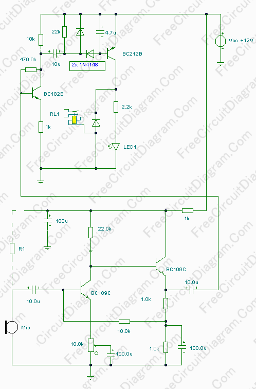
This circuit is not a voice operated switch (VOX) because this circuit is too dumb to differentiate between musical sound or human voice. This is rather a sound activated than voice activated. One interesting application is to control your disco lighting automatically by the musical sound from high power amplifier, when the music signal is dominating the sound space. The schematic diagram is shown below.
You can use either moving coil microphone or condenser microphone for this circuit. For condenser microphone, you have to connect R1 resistor as shown by the dashed line. Choose between 1k5 ad 22k to adjust the sensitivity, or use a 4k7 value if you don’t care with the sensitivity fine tuning. Make sure the electrolytic capacitor is rated for 16 volt or more. The potentiometer shown in the schematic diagram is used to adjust the gain of the pre-amplification. You can adjust this potentiometer to get a proper sound level where the relay would be activated
0 comments:
Post a Comment