STRAIN GAUGE
>> Thursday, April 15, 2010
A strain gauge is a device that is used to measure the strain that occurs in an object. The device was invented in the year 1938 by Edward E. Simmons and Arthur Ruge. The device is still being used in many electronic circuits mainly as the principle sensing element for sensors like torque sensors, pressure sensors, load cells and so on.

Strain Gauge working
Strain Gauge Working Principle
Although strain gauges are available in many shapes and sizes, the fundamental working of this device is the same. They also vary in both shape and size according to their field of application.
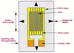
A strain gauge consists of a foil of resistive characteristics, which is safely mounted on a backing material. When a known amount of stress in subjected on the resistive foil, the resistance of the foil changes accordingly. Thus, there is a relation between the change in the resistance and the strain applied. This relation is known by a quantity called gauge factor. The change in the resistance can be calculated with the help of a Wheatstone bridge.
TAKE A LOOK : WHEATSTONE BRIDGE
The strain gauge used is connected to the Wheatstone bridge with the help of an adhesive called cyanocrylate.
The property of the strain gauge not only depends on the electrical conductivity of the conductor, but also in the size and shape of the conductor used. As a matter of fact, the electrical conductivity also depends on the electrical conductance of the foil. This, in turn depends on the material of the conductor. The electrical resistance of the foil changes according to the change in the foil when it is stretched or compressed. The stretching or compressing is considered normal as long as there is no permanent change in the original appearance of the foil. Stretching causes an increase in the resistance from one end to other. Compressing causes a decrease in the resistance from one end of the conductor to another. Basically, the conductor will be a long strip with parallel lines with the condition that a little stress in the path of the orientation of the parallel lines will cause a resultant bigger strain multiplicatively over the effective length of the conductor. Thus a larger resistance change will be obtained.
The force applied to change elongate or shorten the strip can also be calculated with the help of the obtained output resistance.
An ideal strain gauge resistance varies from a few 3 ohms to 3 kilo ohms when it is unstressed. This value will change by a small fraction for the full force range of the gauge. It also depends on the elastic limits of the foil material. If there are forces applied to such an extent that they lose their original shape and size, the strain gauge will no longer be fit to use as a measuring device. So measurement of small fractional changes in the resistance must be taken accurately in order to use the strain gauge as a measuring device.
Applications
The voltage output in accordance to the stress is about a few millivolts. This voltage can be amplified to about 10 volts and can be applied to external data collection systems like recorders or PC data acquisition and analysis systems.
Strain gauges can be used to measure the stress developed in particular machinery and thus is used to mechanical engg. R&D.
The device is used aircraft component testing. Here also the measure of stress is the main issue. For this, strain gauges of very small size are connected to structural members, linkages and so on.
Gauge Factor Equation
The gauge factor of a strain gauge is given be the equation
GF = [∆R/RG]/E
∆R – Resistance produced by the strain
RG – Resistance of gauge before application of stress
E – Strain produced
Types of Strain Gauges
This classification is based on the type of bridge circuit that is connected to the strain gauge. There are mainly three types of connections. They are
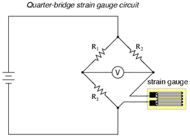
1. Quarter Bridge Strain Gauge Circuit
As shown in the diagram below, the imbalance is detected by the voltmeter in the center of the bridge circuit. The resistance R2 will be a rheostat and hence adjustable. The value of this resistance is made equal to the strain gauge resistance without the application of any force. The resistances R1 and R3 will have equal values. Thus, according to the Wheatstone bridge principle the entire circuit will be balanced and the net force will be zero. Thus the strain will also be zero. Now provide a compression or tension on the conductor and the circuit will be imbalanced. Thus you will get a reading at the voltmeter. Thus, the strain produced in response to the measured variable (mechanical force), is known as a quarter-bridge circuit.

Quarter bridge strain circuit
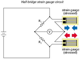
2. Half Bridge Strain Gauge Circuit
As shown in the circuit there are two strain gauges connected. If one of them does not respond to the strain produced it becomes a quarter bridge circuit. If both of them respond in such a way that both the strain gauges experience opposite forces it becomes a half bridge strain gauge circuit. By opposite forces, we mean that a compression on the upper strain gauge makes a stretch on the lower strain gauge. This causes both the gauges to make a better response to strain, thus increasing the response of the bridge to the applied force. As both the strain gauges act opposite and proportionally the response to the changes in temperature will be cancelled thus reducing the errors due to it.

Half bridge strain gauge circuit
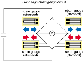
3. Full Bridge Strain Gauge Circuit
In the case of sensitivity, a half bridge strain circuit is more sensitive than a quarter bridge circuit. The sensitivity can be increased if all the elements of the bridge are active. Such a circuit is called full bridge strain gauge circuit. The circuit is also advantageous in the fact that it can be used to bond the complimentary pairs of strain gauges to the testing specimen. Thus, this is considered to be the best bridge circuit for strain measurement. The circuit is also advantageous because of its linearity. That is, the output voltage is exactly directly proportional to the applied force. But in the case of a half bridge and quarter bridge the output voltage is only approximately proportional to the applied force. Take a look at the circuit diagram given below.

Full bridge strain gauge circuit
0 comments:
Post a Comment